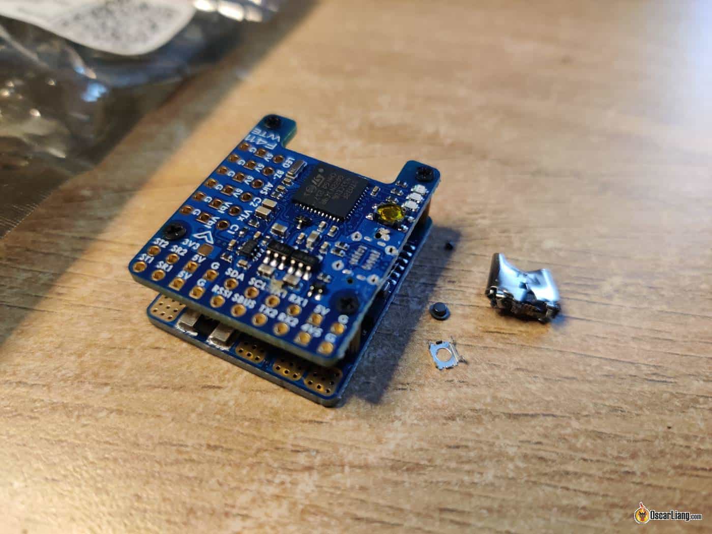
USB port falling off is not uncommon in flight controllers. If your FC has a broken USB port, can’t connect to Betaflight (or INAV Configurator) or flash firmware, here are some fixes you can attempt to save your FC.


Before you begin, check if you can solder the USB port back on though it’s usually not an easy soldering job. In my experience, if your USB port broke off, chances are the tiny solder pads are probably ripped and irreparable, but it’s worth checking, flight controllers are expensive these days!
Get some spare USB ports here:

Connecting FC to Computer via FTDI Adapter
If you just want to connect your FC to Betaflight Configurator (or INAV configurator), all you need is just a FTDI adapter (aka serial converter).
Buy an FTDI adapter here:
For FPV drone builders, it’s a useful tool to have around, I highly recommend getting one. You can also use an Arduino board loaded with custom code (feel free to google it I won’t go into details here), but it’s a lot more complicated than using a $3 plug-and-play FTDI adapter.
Depending on the type of USB connection your flight controller has (i.e. CP2102 or VCP), extra steps might be necessary which I will explain in this tutorial. Almost all modern FC uses VCP connection these days, only some very old FC use CP2102, if you are not sure, this post explains how to identify which one you have.
FC with VCP
If you bought your FC in the last few years, it probably uses VCP connection. It’s not as straightforward as CP2102 because hardware UART’s are not necessary enabled for USB connection by default. The good news is, it’s pretty common that flight controllers are shipped with UART1 enabled for MSP (it allows USB connection), so you can try connecting your FTDI adapter to UART1 first, and see if you can connect to the Configurator.
Try other UART if that didn’t work, if you are lucky one of the UART might have MSP enabled.
Make sure nothing else is connected to that UART, but the FTDI adapter.

FC UART1 is connected only to FTDI adapter
See this example below, “Configuration/MSP” is enabled on UART1, this allows you to use the FTDI adapter to connect it to Betaflight Configurator.

If none of the UART’s have MSP enabled, this is going to get complicated:
- You will have to flash your flight controller with a “rescue” firmware that has MSP enabled on UART1 (with Erase option enabled). But doing this, you will lose the existing FC configuration if you didn’t previously backup your settings.
- And you can’t flash FC firmware using the FTDI adapter, because it needs to be in DFU mode. You will need a STLink Tool that allows you to upload a firmware file (.hex) to the processor using the STM32 ST-Link Utility.
- Buy the ST Link V2 Tool here: Amazon | AliExpress
- Download STM32 ST-LINK utility: https://www.st.com/en/development-tools/stsw-link004.html
So you see, it’s not easy. Anyway if you decide to go ahead, this is how to do it.
Connect FC to STLink Tool to flash rescue firmware:
- 5V to 5V
- GND to GND
- SWCLK (clock) to SWC
- SWDIO (data) to SWD
Here’s a good instructional tutorial about how to use the STLink tool (starts from 4:40): https://youtu.be/5VmhoyL6Z7Q?t=280
One of the main challenges with this method is finding the SWC or SWD pads, they are not always broken out to solder pads on the FC. Check if you can find them on yours before proceeding, if present, they are usually tiny and near the processor for debugging purposes, sometimes not even labelled so you might have to do a bit of “trial and error”.
To be honest most people would have given up at this stage and just get a new flight controller. I think scraping off the solder mask and expose the USB port data traces would be easier if you don’t already have the tools on hand. Keep reading.
FC with CP2102 Chip
If you bought the FC before 2020, chances are USB connection is via the CP2102 chip: UART 1 is reserved for USB connection.
In this case, you need to connect the FTDI Adapter to UART1 (and only UART1), connect these 4 wires:
- TX to RX
- RX to TX
- 5V to 5V
- GND to GND
Make sure nothing else but the FTDI adapter is connected to that UART.

FTDI Adapter on the left, connected to UART1 of my FC on the right
Then connect the FTDI adapter to your computer, you should see a new COM port appear.
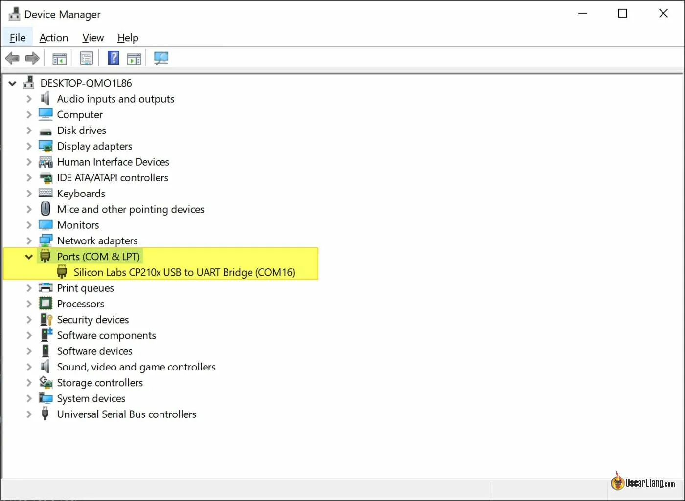
Generally, you shouldn’t need to worry about driver if your computer is already working with your flight controller, which means driver is already installed. But if driver is needed, you will see a warning sign icon on that COM port. You can normally get the driver file on the product page of your FTDI adapter, or simply google the type of adapter you have.
In Betaflight/INAV Configurator, select this COM port and hit the Connect button. That’s it.
How to Fix Damaged USB Port
If FTDI adapter method fails, and you cannot flash rescue firmware, you can try attaching a breakout board to the FC. The idea is to find the D+ and D- pads in the USB port, and connect them to a USB breakout board. You can use it just like a normal USB port.
You can buy some USB breakout boards here, very nice to have some spare:

If those D+ and D- pads on the FC are not ripped, you can simply solder wires to those pads. Connections:
-
- D+ to D+
- D- to D-
- VBUS to any 5V on the FC
- GND to GND
Here are the pinout of a micro USB breakout board, flight controllers use the same 5-pin connector has the same pinout:

Here’s the pinout of a USB-C port, there are normally 16 pins (two rows of 8-pin), D- and D+ are usually the center two pins on both top and bottom row rotated 180-degree:

If those pads are ripped, you can try to follow the copper traces and find where they go, usually end up at a small capacitor which is relatively easy to solder to. Here’s an example where D- and D+ are on a Matek FC.

If you can’t find that, you can scrap off the solder mask and expose the copper traces for D- and D+, and solder the wires to them. I use a small file for that.


If you want those wires to stay on the FC permanently you definitely want to glue the cables and solder joints securely so you don’t break those super tiny solder joints.
Edit History
- May 2018 – article created
- Apr 2021 – Betaflight now offers USB Rescue firmware in the firmware flasher, you no longer need to download it manually from google drive
- Feb 2023 – Added info about flashing FC without USB port, diagrams of USB port pinout
- July 2026 – Updated links